Pouch cell
The "pouch cell" is generally regarded as a "flexible" cell - not only, but primarily because of the aluminium and plastic composite foil housing.
The housing foils are insulatingly coated with polymers on the inside as well as on the outside. The advantages of the pouch cell are numerous and of course have to be weighted according to the application.
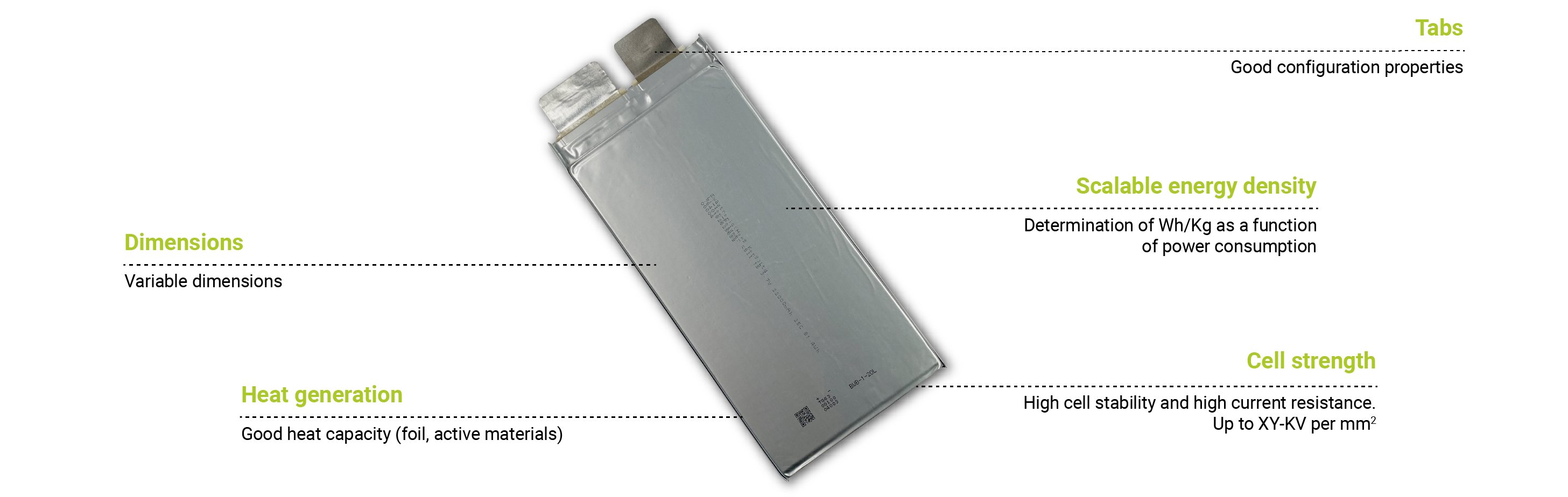
We would like to highlight the following strengths of the pouch cell which offer advantages over other enclosures and designs in almost every application:
Scalable cell shape and size
The geometry of the cell can be chosen almost freely and the size or dimensions are freely scalable.
Good heat dissipation and cooling options
Lithium-ion cells are generally sensitive to less than optimal temperature conditions - the pouch cell, however, has its own good heat dissipation and offers optimal conditions for passive or active cooling systems in terms of surface and design.
High energy density / power density
Due to the stacking method and the corresponding active materials, pouch cells achieve a high gravimetric as well as volumetric energy density. The capacity or energy content increases while the voltage remains constant. By adjusting the cathode and anode active material, the charge and discharge rates can be decisively influenced and adapted to the power requirement.
Stacking options
The pouch cells can be "stacked"; please note that no additional pressure is exerted on the cell surfaces.
Flexible manufacturing costs
Due to the combinable form factors for different requirements and designs of the cell, a variety of different pouch cells (depending on the production line and mould`s) can be manufactured within the same production line.
Pack assembling / Busbars
The busbar connects individual cells to each other. Depending on the design of the finished battery, cells connected in series and bricks, different types of busbars are used.
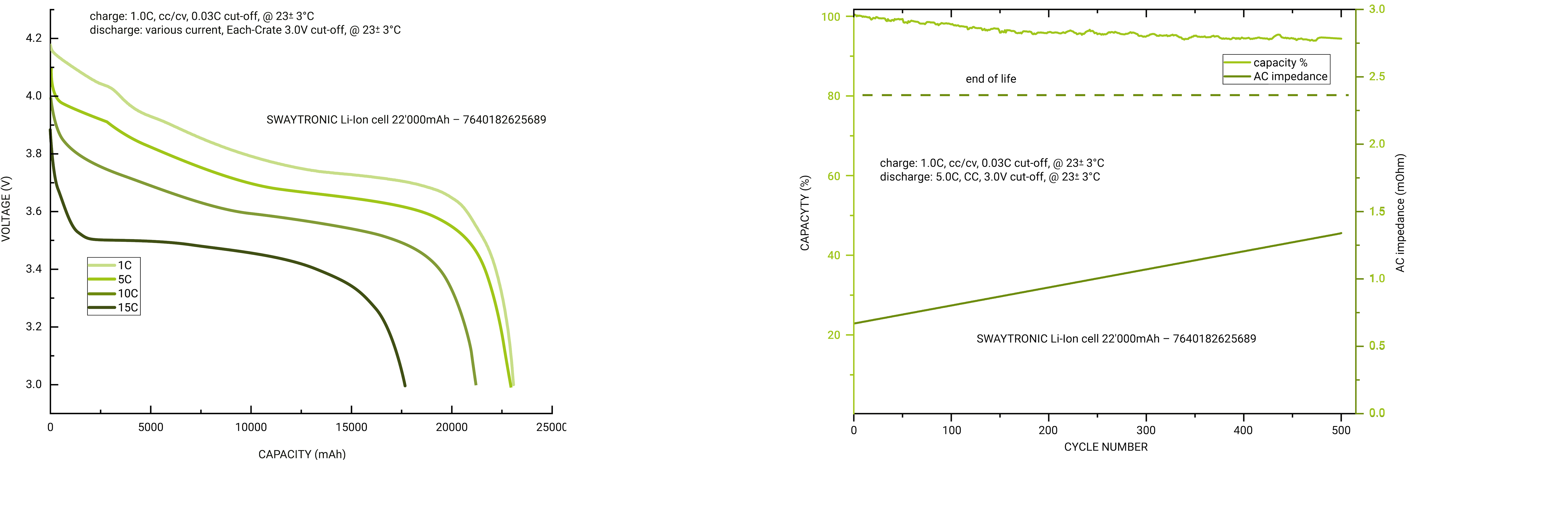
We test our cells in the "Discharge Mode" within different power classes / C rates. The available amount of energy of a cell in Ah varies depending on the cell and discharge rate. Voltage levels under load and their progression are also visible.
The "life cycle" of a cell, or the EoL (End of Life) time depends on various factors and selected or adjusted values. We test our cells regularly, in this example with 500 charge and discharge cycles. With almost 97% remaining capacity after 500 cycles, this result is impressive.
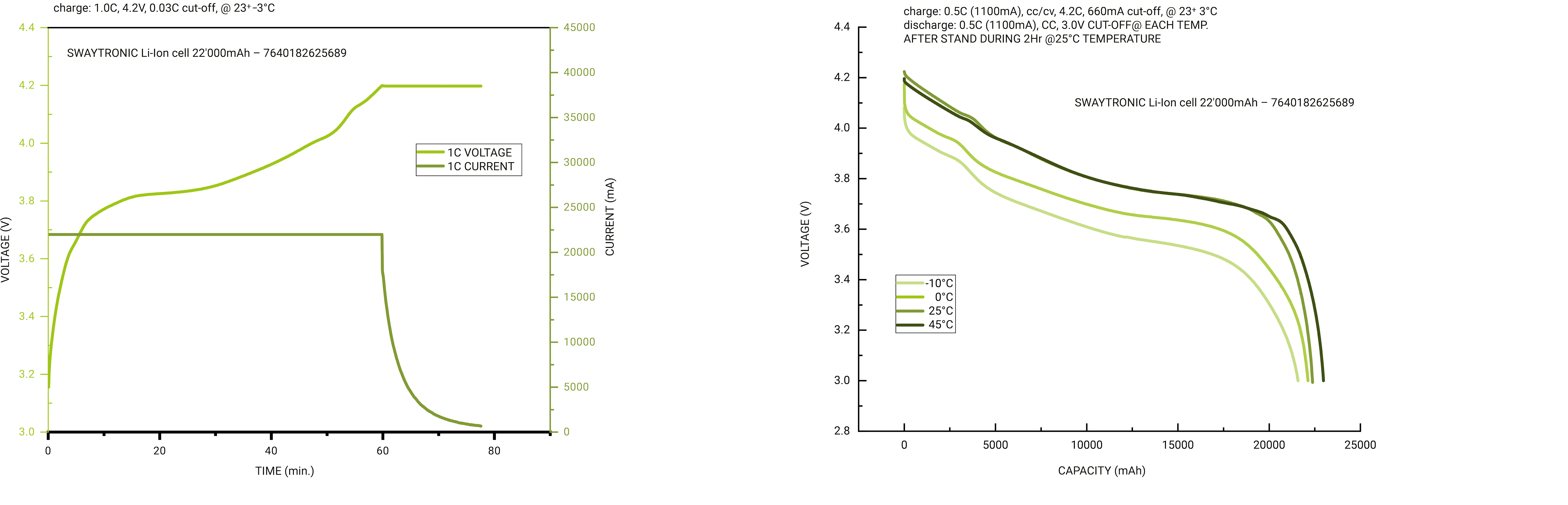
By means of our charging diagrams, we test the cell behaviour during CC-CV charging within the parameters specified by the cell.
Depending on the project specifications, the subsequent connection and use of the cell, we check the relevant values and their development in order to ensure a safe and efficient charging process.
The outside temperatures, i.e. the conditions for a cell / pack, have a significant influence. The discharge behaviour, as well as many other factors.
With our temperature chamber, we are able to simulate the corresponding ambient conditions in order to simulate the most accurate possible image of the subsequent discharge curves in real conditions.

A selection of our "cell moulds
We work with different cell moulds, which enable us to produce different performance classes of pouch cells with defined form factors. In addition to the electrode foil and its structural properties, we also modify the inner life of the cell with appropriate additives.
In the following table you will find a selection of project cells, which represent a large field of size, weight and power-specific data. We are able to further develop and adapt all existing cells in the direction you require in terms of performance data, etc.
If no suitable cell mould is available, we will create an individual mould according to your technical specifications.
| EAN | Voltage (V) | Capacity (mAh) | Discharge rate C |
Energy density Wh/KG |
Dimensions (excl. tabs) |
Internal resistance mΩ < |
Cells Tab (+) | Cells Tab (-) | Weight g | Certification | MSDS | ||||||
|---|---|---|---|---|---|---|---|---|---|---|---|---|---|---|---|---|---|
| L | B | H | L | B | D | L | B | D | |||||||||
| 7640182628291 | 3.8 | 32000 | 15/30 | 121.6 | 201 | 118.5 | 11.1 | <2mOhm | 25 | 35 | 0.2 | 25 | 25 | 0.2 | 548 | CE EN 62133; UN38.3; DGM CE-EMC; EN61000-6-3; EN61000-6-1 | Yes |
| 7640370543221 | 3.9 | 30000 | 5/10 | 117 | 198 | 98 | 11 | <2mOhm | 25 | 35 | 0.2 | 25 | 25 | 0.2 | 575 | CE EN 62133; UN38.3; DGM CE-EMC; EN61000-6-3; EN61000-6-1 | Yes |
| 7640370543337 | 3.8 | 25000 | 3/6 | 95 | 250 | 95 | 70 | <1.3mOhm | 25 | 35 | 0.2 | 25 | 25 | 0.2 | 378 | CE EN 62133; UN38.3; DGM CE-EMC; EN61000-6-3; EN61000-6-1 | Yes |
| 7640370543351 | 3.8 | 25000 | 2/5 | 95 | 190 | 90 | 11 | <1.3mOhm | 25 | 35 | 0.2 | 25 | 25 | 0.2 | 430 | CE EN 62133; UN38.3; DGM CE-EMC; EN61000-6-3; EN61000-6-1 | Yes |
| 7640370543320 | 3.8 | 24000 | 3/6 | 91.2 | 192 | 91 | 11 | <1.3mOhm | 25 | 35 | 0.2 | 25 | 25 | 0.2 | 385 | CE EN 62133; UN38.3; DGM CE-EMC; EN61000-6-3; EN61000-6-1 | Yes |
| 7640370543658 | 3.7 | 22000 | 30/60 | 81.4 | 192 | 90 | 10.5 | <2mOhm | 25 | 35 | 0.2 | 25 | 25 | 0.2 | 398 | CE EN 62133; UN38.3; DGM CE-EMC; EN61000-6-3; EN61000-6-1 | Yes |
| 7640182628307 | 3.7 | 22000 | 25/50 | 81.4 | 193 | 90 | 11 | <2mOhm | 25 | 35 | 0.2 | 25 | 25 | 0.2 | 405 | CE EN 62133; UN38.3; DGM CE-EMC; EN61000-6-3; EN61000-6-1 | Yes |
| 7640182625689 | 3.7 | 22000 | 25/50 | 81.4 | 193 | 90 | 11 | <2mOhm | 25 | 35 | 0.2 | 25 | 25 | 0.2 | 405 | CE EN 62133; UN38.3; DGM CE-EMC; EN61000-6-3; EN61000-6-1 | Yes |
| 7640370543993 | 3.7 | 22000 | 15/20 | 81.4 | 190 | 90 | 11 | <1.3mOhm | 25 | 35 | 0.2 | 25 | 25 | 0.2 | 430 | CE EN 62133; UN38.3; DGM CE-EMC; EN61000-6-3; EN61000-6-1 | Yes |
| 7640370543368 | 3.7 | 22000 | 8/20 | 81.4 | 190 | 90 | 11 | <1.2mOhm | 25 | 35 | 0.2 | 25 | 25 | 0.2 | 430 | CE EN 62133; UN38.3; DGM CE-EMC; EN61000-6-3; EN61000-6-1 | Yes |
| 7640370543344 | 3.7 | 20000 | 15/20 | 74 | 190 | 90 | 11 | <1.5mOhm | 25 | 35 | 0.2 | 25 | 25 | 0.2 | 390 | CE EN 62133; UN38.3; DGM CE-EMC; EN61000-6-3; EN61000-6-1 | Yes |
| 7640370543405 | 3.7 | 16000 | 30/60 | 59.2 | 176 | 75 | 11 | <2mOhm | 25 | 35 | 0.2 | 25 | 25 | 0.2 | 300 | CE EN 62133; UN38.3; DGM CE-EMC; EN61000-6-3; EN61000-6-1 | Yes |
| 7640182628260 | 3.7 | 16000 | 25/50 | 59.2 | 176 | 75 | 11 | <2mOhm | 25 | 35 | 0.2 | 25 | 25 | 0.2 | 300 | CE EN 62133; UN38.3; DGM CE-EMC; EN61000-6-3; EN61000-6-1 | Yes |
| 7640370540374 | 3.7 | 13000 | 30/60 | 48.1 | 193 | 90 | 8.1 | <1mOhm | 25 | 35 | 0.2 | 25 | 25 | 0.2 | 300 | CE EN 62133; UN38.3; DGM CE-EMC; EN61000-6-3; EN61000-6-1 | Yes |
| 7640370542118 | 3.7 | 13000 | 25/50 | 48.1 | 160 | 70 | 11.2 | <2mOhm | 25 | 35 | 0.2 | 25 | 25 | 0.2 | 245 | CE EN 62133; UN38.3; DGM CE-EMC; EN61000-6-3; EN61000-6-1 | Yes |
| 7640370542095 | 3.7 | 10000 | 25/50 | 37 | 150 | 59 | 10 | <2mOhm | 25 | 35 | 0.2 | 25 | 25 | 0.2 | 195 | CE EN 62133; UN38.3; DGM CE-EMC; EN61000-6-3; EN61000-6-1 | Yes |
| 7640370542088 | 3.7 | 8000 | 25/50 | 29.6 | 140 | 50 | 8.3 | <2mOhm | 25 | 35 | 0.2 | 25 | 25 | 0.2 | 174 | CE EN 62133; UN38.3; DGM CE-EMC; EN61000-6-3; EN61000-6-1 | Yes |
| 7640182623654 | 3.7 | 1600 | 200/400 | 5.92 | 74 | 34 | 10 | <3mOhm | 25 | 22 | 0.2 | 25 | 17 | 0.2 | 48 | CE EN 62133; UN38.3; DGM CE-EMC; EN61000-6-3; EN61000-6-1 | Yes |
| 7640370543283 | 3.9 | 5000 | 5/10 | 19.5 | 95 | 60 | 6.5 | <2mOhm | 25 | 20 | 0.2 | 25 | 15 | 0.2 | 75 | CE EN 62133; UN38.3; DGM CE-EMC; EN61000-6-3; EN61000-6-1 | Yes |
| 7640182623661 | 3.8 | 1450 | 90/180 | 5.51 | 75 | 34 | 8 | <3mOhm | 25 | 21 | 0.2 | 25 | 16 | 0.2 | 42 | CE EN 62133; UN38.3; DGM CE-EMC; EN61000-6-3; EN61000-6-1 | Yes |
| 7640182623678 | 3.7 | 1100 | 100/200 | 4.07 | 77 | 34 | 6 | <3mOhm | 25 | 20 | 0.2 | 25 | 15 | 0.2 | 32 | CE EN 62133; UN38.3; DGM CE-EMC; EN61000-6-3; EN61000-6-1 | Yes |